Scratchbuilding Techniques:
Steve Okeefe's Inline Motor Bracket
by Steve Okeefe, Feb. 6, 2003
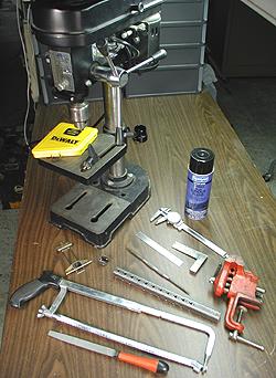 Here's an inexpensive way to make your own custom inline motor brackets
from scratch. Being made of steel, they are not only tremendously strong,
but lighter than an equivalent size and shape brass bracket as well.
While the fabrication process is simple and straightforward, it does
require some skill in laying out the repeating pattern of holes, and
drilling those holes accurately.
Basic layout tools you'll need are
a straightedge (a six inch machinist's rule works best), a small square
(such as a three inch machinist's square), a scriber and a centerpunch.
Having a dial caliper wouldn't hurt. Layout dye is also very helpful,
but armature dye (example: Lucky Bob's) will work just fine.
Cutting and shaping tools you'll need are a bench vise, a hacksaw (or a Dremel
with a reinforced cutoff wheel), a six to eight inch flat file,
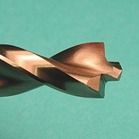 and a selection of sharp drill bits up through at least one-quarter inch
(split-point bits are preferred). A word about drill bits: They are like
X-acto knife blades, which is to say they dull after a while, and dull
drill bits will ruin this project for you. Do yourself a favor and
buy new ones.
Use of a drill press is highly
recommended in order to get the holes as straight and square as possible.
If you use the right tools and work carefully, this will be easier to
do than to describe, so if I haven't scared you off yet, let's get started.
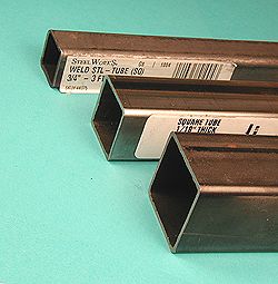
Visit your friendly local hardware mega-store, and pick out some square steel tubing
(and some new drill bits). The tubing is usually available in 3/4, 1, and 1 1/4 inch sizes,
as shown in the picture. The 1-inch and the 1 1/4 inch size works best for 1/24 scale cars,
and the 3/4 inch size is great for either 1/32 or 1/24 scale.
 Select your material based on the "flatness" of the sides.
Usually one or more of the sides are bowed-in slightly, and
in the 1-inch and 1 1/4 inch size, there is usually a weld line on one side.
You want a piece with as many of the sides as flat as possible.
For the really intense scratchbuilders among us, you can get 3/4 or 1-inch
square stainless steel tubing from an outfit called Small Parts
(www.smallparts.com).
There are some drawbacks, however. It's pricey, and
it's mail order, which means you can't hand pick the material.
It is best to lay out the pattern and drill the holes for several brackets at once,
because it is much easier than doing them one at a time (I did ten).
Determine which of the four sides of the tube has the weld line
(in the 3/4 inch size, pick the size that is bowed-in the worst),
and mark it, if necessary. You can easily find the welded side by feeling
for the weld bead on the inside of the tube.
This "bad" side
will be cut out to make the "U" shaped bracket.
Using your file, square the end of the tube so you can use it as a reference point
for layout measurements.
Apply layout dye to the side opposite the "bad" side,
and also one of the two remaining sides.
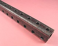 Take your time doing this next part, because accuracy is critical.
On the side opposite the "bad" side, scribe a centerline
along the length of the tube using the straightedge,
this will be the side the motor mounts on. On the remaining side
with the layout dye, scribe a line along the length of the tube
a minimum of 9/16 inch from the motor mounting side. This line will be
used to locate the drilling marks for the axle bearing holes.
If you want lightening holes, lay out their positions now
so they can be drilled at the same time as the bearing and
motor mounting holes.
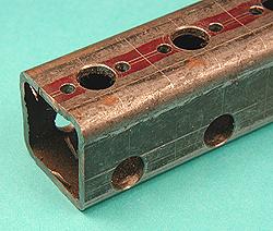 Next, lay out the height of the finished motor brackets on the motor mounting side
using the square, leaving a generous space between the bracket blanks for
the hacksaw or Dremel cutoff wheel kerf. Along the centerline on
the motor mounting side, lay out the position of the motor bearing hole
and the two screw holes on each bracket blank. On the remaining side
with the scribed line, lay out the positions of the holes for the axle bearings.
Remember the axle bearing holes MUST be in line with the motor bearing hole
(unless you intend to use hypoid gears!).
Centerpunch each hole position carefully, as the punch mark is
intended to guide the drill bit. Drill all the holes, being certain
the bit doesn't "wander" before biting in. Drill both axle-bearing
holes in each bracket blank at the same time by drilling all the way
through both sides of the tube. This is where using the drill press
makes things much easier. Chamfer the holes to clean them up, and
check to see they are all positioned accurately.
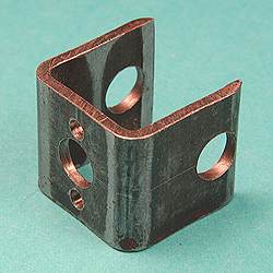 After cutting each individual blank off the tube with a hacksaw or cutoff wheel, finish it
by cutting out the "bad" side. File the bottom edges
so that the motor and axle bearing holes are the correct distance
from the bottom edge. If you drilled the holes accurately, the bracket
sides will now stand square to the jig block.
When shaping the top edge, avoid cutting within about 1/8 inch
of the vertical centerline on the front (motor mounting) side, it's
full of holes and already the weakest part! To lower the center of
gravity and further lighten the bracket (in addition to the previously
drilled lightening holes), you can cut down the corners and both
of the sides. Just don't reduce the overall cross section of the bracket
material by more than about half.
Soldering chassis rails and other parts to this thick section bracket
is not difficult if you remember to tin the bracket first, use soldering
flux, and heat the bracket more than the (lighter) parts you're
soldering to it. Also, using a thousand degree, 3/8 inch chisel tip Ungar
or Hakko iron is highly recommended. Tip: Tin the entire surface of
the finished bracket, this will protect it from rust.
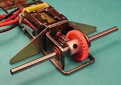 One more thing, because this bracket is 1/16 inch thick, if you
want to mount the motor with screws, they will have to be a bit longer.
For can mounted motors, I have for many years used 2-56 hex socket screws
and nuts instead of self tapping screws, with the nuts soldered
inside the bottom of the can. The trick to doing this is to use
aluminum screws to hold the nuts in place, and solder them in
with high temperature solder (95% tin, 5% antimony), then solder
the bearing in with low temperature solder (60% tin, 40% lead)
using a low temperature iron.
--Steve Okeefe