Reader's Gallery 102 |
Steve Okeefe's Collection: Chaparral with
Vintage 1:24 Inline Chassis
Steve Okeefe sent these pictures of a recent ebay acquisition, a 1965-66 Chaparral on a scratchbuilt
inline chassis. The original builder of this chassis is unknown. Note the diagonal frame rail -
this chassis is from the transition period as builders moved from the space frame to the flat chassis.
Thanks for contributing this vintage specimen, Steve. --tja
The rest of this chassis review is written by Steve Okeefe. Steve writes:
Not being a collector, or a particularly big fan of the Chaparral, I wouldn't normally go after something
like this; however this one caught my eye. Likely built in late 1965 or some time in 1966, the overall
characteristics of the car, among them weight, dimensions and proportions, are fairly typical for the time,
but the thinking that went into the design is not.
|
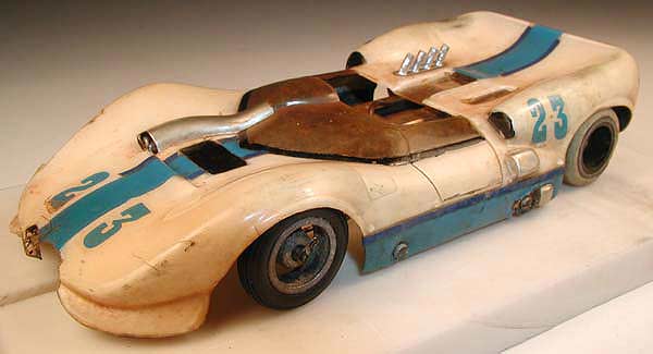 |
Above: A Chaparral 2A, complete with ventilation duct through the windshield.
Vintage 1965, the 2C did not have this duct, but had instead the now famous "flipper" tail.
The body is scale size in thick butyrate, with a 3-3/4" wheelbase, and barely 2-7/8" wide.
Total weight is about 92 grams (roughly 3-1/4 oz.) once pickup braid and interior are added.
|
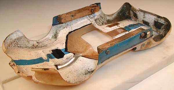 |
Above: Underside of body. Hand painted as was common practice back then, the body has seen its share
of slot racing fun. Note the wood blocks used as part of a quick release body mount system. Clever idea,
but it is common knowledge wood has no place in slot car chassis construction!
|
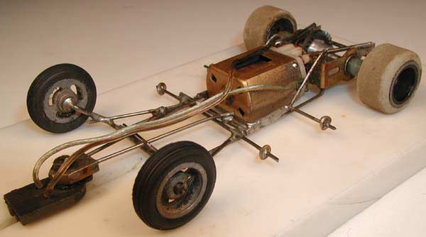 |
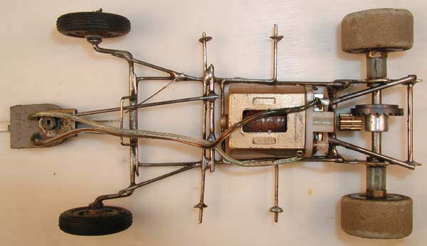
Above: Chassis quarter view. Front wheels have 15/16" x 1/4" ribbed tires on three spoke threaded
magnesium hubs with brass reducers. The hubs appear to be Mila Miglia units. Rear wheels are standard Russkit,
1/2" wide with gray rubber on anodized, threaded and drilled aluminum hubs. Original rear tire diameter
is unknown, but was probably 15/16".
|
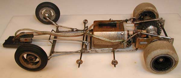 |
Above: Chassis left side. The center section has an unusual feature; consisting of a single piece
of .047" piano wire with no less than ten bends! Beginning with the main chassis rail attachment
to the drop axle, you can trace the wire back to the motor bracket, up through the bracket, diagonally
back down to the main rail, forward to the drop arm hinge, and then diagonally outward to form the
front axle brace; five bends on each side.
|
 |
Above: Chassis top. The downward sprung drop arm is an uncomplicated affair consisting of two short,
relatively straight pieces of .047" piano wire with a Dynamic pillow block to hold the pickup guide.
The hinge is 1/16" Nickel plated brass tubing with a .032" piano wire hinge pin. Note the
whole drop arm is above the main chassis rails, which form the down stop, the up stop being an added
loop of .032" piano wire.
|
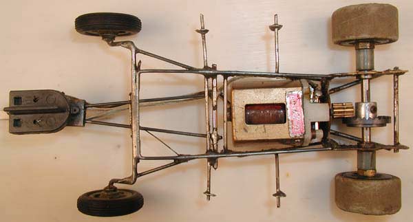 |
Above: Chassis bottom. Horsepower is a clockwise rotation Russkit 23. Can and rivet-fastened endbell
appear completely stock, however the armature, and magnet installation, is not. Rewound with what looks
like 29 gauge wire, epoxied, balanced, with a polished stack and shimmed magnets, it would have been
rather hot for the period. The well worn brushes indicate it saw a fair amount of use.
|
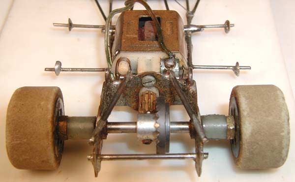 |
Above: Chassis rear. Looks like a K&B motor bracket, of a type supplied with their yellow
Wildcat 16Ds. The rear axle rides in ball bearings, driven by a Cox 25 tooth crown and a 9 tooth
brass pinion. I'd say, unless this is not the original crown gear, this car was geared way too
high (2.78:1), and was probably a real handful to drive!
--Steve Okeefe, Nov. 21, 2004
|
|
Previous Chassis |
Reader's Gallery Index |
Next Chassis
|